How to Adjust the Gear Shift Lever on a 2001 Jeep Grand Cherokee 4.0 UPDATED
How to Adjust the Gear Shift Lever on a 2001 Jeep Grand Cherokee 4.0
1993 Jeep Cherokee
TRANSMISSION SERVICING
Chrysler Corp. Automatic Transmission
Jeep; Cherokee, Thou Cherokee, Chiliad Wagoneer, Wrangler IDENTIFICATION
JEEP Automatic TRANSMISSION APPLICATIONS TABLE
Model Transmission
Except Wrangler Aisin Warner AW-4
Wrangler Chrysler 32RH (Formerly A-999)
LUBRICATION
SERVICE INTERVALS
Manual
Check fluid level and condition of fluid at 7500 mile intervals. Alter fluid, replace filter and suit bands at 30,000 miles or xxx month intervals.
Transfer Case
Check transfer case fluid every 7500 miles and supervene upon fluid every 30,000 miles or 30 month intervals.
CHECKING FLUID LEVEL
Manual
Park vehicle on a level surface and apply parking restriction. With engine idling at normal operating temperature, move transmission selector lever through all gears, ending in Neutral (Park for AW-4 transmission). Check fluid level. Fluid level should exist betwixt Full and Add together marker on dipstick. Add fluid every bit needed. DO Not overfill.
Transfer Case
Remove fill plug. Check oil level. If level is not upwards to bottom of fill plug opening, add lubricant.
RECOMMENDED FLUID
Manual
Aisin Warner AW-4 transmissions and transfer cases use Mercon type ATF. Chrysler 32RH transmissions utilize Dexron-Two blazon ATF.
Transfer Instance
Transfer cases use same fluid equally attached transmission.
FLUID Capacity
Notation: Transmission and converter capacities are guess.
Always determine fluid level by reading on dipstick, rather than amount of fluid added. See appropriate REFILL CAPACITIES tabular array.
TRANSMISSION REFILL CAPACITIES TABLE
Application Qts. (50)
AW-4 eight.v (viii.0)
32RH 8.0 (7.half dozen)
TRANSFER CASE REFILL CAPACITIES Tabular array
Application Pts. (L)
Model 231 3.3 (1.5)
Model 242 3.0 (ane.iv)
Model 249 3.0 (ane.4)
DRAINING & REFILLING
Transmission
-
Position large drain pan under transmission. Loosen oil
pan bolts, tap pan to break it loose and allow fluid to drain. Remove
pan and oil filter. Install NEW filter on bottom of valve body and
tighten retaining screws to 35 INCH lbs. (4 N.grand). Clean oil pan and
install with NEW gasket. Tighten bolts to 150 INCH lbs. (17 N.m). -
Refill transmission with approximately 5 qts. (four.7L) of
ATF. Start engine and allow to run at curb idle. With vehicle on level
surface, engine idling and parking brake applied, move shift selector
lever through all gear ranges, ending in Neutral (Park for AW-4
transmission). -
Recheck fluid level when transmission reaches normal
operating temperature. Add fluid to FULL mark on dipstick.
Transfer Instance
Remove drain plug from transfer case. Remove fill plug for easier draining. With fluid fully drained, reinstall bleed plug. Fill transfer instance and install fill plug. Tighten drain plug and fill plug to 20 ft. lbs. (27 N.m).
ADJUSTMENTS
Note: Bands on the AW-4 transmission are non adjustable. If slippage occurs, bands must be replaced.
KICKDOWN (FRONT) Band
32RH
ane) Locate kickdown band adjusting screw on left side of case
(well-nigh throttle lever shaft). Meet Fig. 1. Loosen adjusting screw lock
nut and back off 4-v turns. Ensure adjusting spiral turns freely in example.
two) Tighten adjusting screw to 72 INCH lbs. (8 N.m). If
Adapter Extension (J-24063) is used, tighten adjusting spiral to l
INCH lbs. (5 N.m). Back off adjusting screw two ane/2 turns. Agree
adjusting spiral and tighten lock nut to 30 ft. lbs. (41 N.grand).
![]()
From Cooler
Fig. 1: Adjusting Kickdown (Front) Band Courtesy of Chrysler Corp.
LOW-REVERSE (REAR) Band (TYPICAL)
32RH
-
Heighten and support vehicle. Drain manual fluid and
remove oil pan. Locate depression-reverse ring adjusting screw on rear servo
lever. See Fig. ii. Loosen adjusting screw lock nut. Dorsum off lock nut
5-6 turns. -
Tighten adjusting screw to 72 INCH lbs. (8 Due north.m). Back off
adjusting screw four turns. Concur adjusting spiral and tighten lock nut to
25 ft. lbs. (34 N.m). Install oil pan and fill transmission with
fluid.
![]()
Fig. two: Adjusting Low-Reverse (Rear) Band (Typical) Courtesy of Chrysler Corp.
THROTTLE Cablevision
With ignition off, fully retract cable plunger. Press cablevision push button down and push cablevision plunger inward. Rotate throttle lever to broad open throttle position. Cablevision will ratchet to correct position. Release throttle lever. Cable is at present adapted.
SHIFT LINKAGE
AW-4
-
Place gearshift lever in Park and enhance vehicle. Using a
small screwdriver, unlock shift control cable by releasing "U" shaped
cable adjuster clamp. Remove cable from mounting bracket. -
Move transmission shift lever rearward until fully seated
into Park detent. Ensure that drive shaft cannot be rotated. Snap
control cable into cablevision mounting bracket and replace "U" shaped cablevision
adjuster clamp. Lower vehicle and verify engine starting. Engine
should outset only with shifter in Park or Neutral.
32RH
-
Loosen shift rod trunnion jam basics at transmission lever.
Remove shift rod-to-bellcrank lock pin. Disengage trunnion and shift
rod. Place selector lever in Park and lock steering cavalcade. Move
transmission shift lever to full rear Park position. -
Adapt shift rod trunnion to obtain gratuitous pin fit in
bellcrank arm. Tighten jam basics. On vehicles with shift lever on
cavalcade, ensure linkage lash is eliminated by pulling down on shift rod and pushing up on outer bellcrank when tightening jam basics.
3) Check steering column lock for ease of functioning. Ensure engine starts in Neutral or Park simply. If starter engages in any drive gear, or does not work in Neutral or Park, check for proper shift linkage adjustment or faulty neutral safety switch.
PARKING LOCK Cablevision
AW-iv
-
Shift transmission to Park. Turn ignition switch to lock
position. Remove center panel bezel to access cablevision aligning. -
Pull cable lock button upwards to release cable. Meet Fig. three.
Pull cable forrad and release. Press lock button downwards until information technology snaps
in place.
![]()
90B04353
Fig. 3: Adjusting Shift Cable Courtesy of Chrysler Corp.
-
Verify adjustment by trying to move shifter. Shifter
push and/or shifter should not motility. -
Plough ignition on. Move shifter to Neutral. If ignition
switch cannot exist turned to Lock position, cable is adjusted. Repeat
this step with shifter in Drive.
NEUTRAL SAFETY SWITCH
AW-iv
-
With transmission linkage properly adjusted, switch allows
starter operation in Park or Neutral only. -
To test switch, remove wire connector. Using ohmmeter,
ensure continuity exists between proper terminals with manual at
specified gear range. Meet Fig. four. Replace switch if faulty. -
To replace switch, disconnect wire connector. Curve switch
washer lock tabs upwardly and remove switch retaining nut and adjusting
bolt. Remove switch assembly.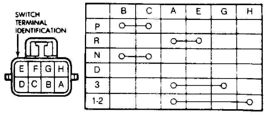
TESTING SWITCH
-
To install, disconnect shift linkage from manual
shift lever. Rotate shift lever all the mode rearward and then forward
2 detent positions. This is the Neutral position. Install switch
associates. -
Install adjusting bolt finger tight but. Install lock
washer and retaining nut. Tighten nut to 61 INCH lbs. (7 N.g). Rotate
switch to align standard line with groove of manual valve shaft. See
Fig. 4. Tighten adjusting bolt to 108 INCH lbs. (13 N.m). Bend over
lock tabs and install remaining components.
![]()
Fig. iv: Testing & Adjusting Neutral Safety Switch Courtesy of Chrysler Corp.
32RH
1) With transmission linkage properly adjusted, switch should
allow starter operation in Park or Neutral but.
-
To exam switch, remove wire harness and test for
continuity between center pin of switch and transmission example.
Continuity should only exist when transmission is in Park or Neutral. -
Shift transmission into Reverse. Check for continuity
betwixt 2 outer switch terminals. Continuity should exist with
transmission in Contrary just. With transmission in Reverse, cheque
continuity between each outer switch terminal and manual example.
No continuity should exist between terminals and manual case. -
To replace switch, disconnect wire connector and unscrew
switch from instance. Motion selector lever to Park and Neutral positions
and ensure switch operating fingers are centered in switch opening. -
Install switch and NEW seal in case. Tighten switch to 24
ft. lbs. (33 N.m). Check fluid level and add equally needed.
TORQUE SPECIFICATIONS
TORQUE SPECIFICATIONS Table
Application Ft. Lbs. (North.k)
Kickdown (Front end) Band Lock Nut thirty (41)
Low-Contrary (Rear) Ring Lock Nut 25 (34)
Neutral Rubber Switch (32RH) 25 (34)
Oil Pan Bolts 13 (18)
Transfer Example Make full Plug 20 (27)
INCH Lbs. (N.m)
Filter
AW-iv 84 (x)
32RH 35 (four)
Kickdown (Front) Band (1) 72 (8)
Low-Opposite (Rear) Ring 72 (eight)
Neutral Safe Switch (AW-four)
Retaining Nut 61 (7)
Adjusting Bolt 108 (13)
(1) - If adapter extension is used, tighten to fifty INCH lbs. (5 Northward.m). See text for complete adjusting procedure.
DOWNLOAD HERE
How to Adjust the Gear Shift Lever on a 2001 Jeep Grand Cherokee 4.0 UPDATED
Posted by: davidanindereng.blogspot.com

Comments
Post a Comment